
DALI-2: digital lighting control for real projects
How DALI-2 works, what separates it from 0-10 V, KNX and wireless, and how to specify a digital lighting installation without the usual design mistakes.
On most projects, the decision about how lighting will be controlled gets made late — once the fixtures are already bought and the switchboard is already built. At that point the options collapse to switching by circuit, which is precisely what the lighting design was trying to avoid.
DALI-2 is one answer to that problem, and it is worth understanding before you specify, not after.
What DALI is and what DALI-2 added
DALI stands for Digital Addressable Lighting Interface: a digital, addressable interface for lighting control, standardised under IEC 62386. Its central idea is simple and powerful — every driver, every sensor and every keypad has its own address and communicates over a digital bus. Grouping stops being a wiring question and becomes a configuration question.
DALI-2 is the evolution of the standard, and its main contribution is not a new feature but something duller and more important: it extended certification to input devices and application controllers, not just to control gear — drivers and ballasts — as before.
That difference translates into something practical. The DALI Alliance tests products and maintains a public database of certified equipment. Specifying DALI-2 and verifying certification substantially reduces the risk that one brand’s sensor will not understand another brand’s driver, which was the classic complaint about first-generation DALI installations.
There is also D4i, an extension for DALI inside the luminaire, aimed at having the fixture itself report energy and diagnostic data. It becomes relevant when the project wants asset management rather than control alone.
How the bus works
The DALI bus is two wires carrying data and the bus’s own power. Importantly, it does not power the luminaire — that comes through its normal supply. So the control wiring is functionally independent of the power wiring, even when it shares containment.
And it shares containment without trouble, because the DALI bus is specified with mains-rated insulation. That is a practical advantage over low-voltage control systems that require physical separation: fewer trays, fewer routes, fewer conflicts on site.
The figures that govern each line’s design:
- 64 individual addresses per line.
- 16 groups and 16 scenes per device.
- 250 mA maximum bus current, supplied by a dedicated power supply.
- Cable runs commonly up to 300 m, with bus voltage drop as the real limit.
Exceeding any of those is not something you force through; you divide into more lines, each with its own supply and interface. That sizing is the part of the design most often neglected.
The bus is also bidirectional. Devices do not only receive commands, they report status. A driver can report that a lamp has failed or how many hours it has run. In a building with hundreds of luminaires, that telemetry changes maintenance entirely — you go from waiting for a complaint to knowing which point failed and where it is.
Addressing, groups, scenes and dimming
During commissioning, each device is assigned its short address and allocated to the relevant groups. From there:
- Individual address: to control one specific luminaire.
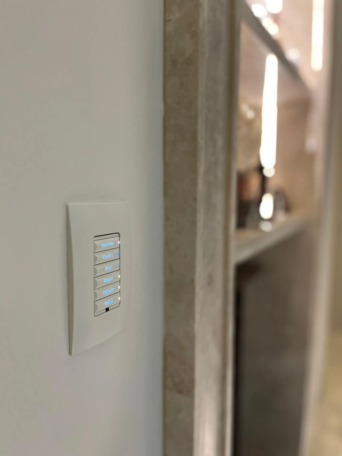
- Groups: logical sets — wall washers, desks, circulation — reorganised by configuration, without touching a single cable.
- Scenes: predefined level states for each device, invoked with a single command.
- Dimming: attenuation follows a logarithmic curve, designed to match how the eye perceives changes in light rather than the electrical curve. It is why well-tuned DALI dimming feels smooth while poorly resolved analogue dimming feels stepped.
The design consequence is the one that matters: zoning is decided in software. If the client reorganises the offices two years later, you reprogram groups. With circuit-based control, you rebuild the switchboard.
DALI-2 against the alternatives
Against 0-10 V. 0-10 V is analogue and has no addressing: every dimmable zone needs its own control pair run back to the dimmer, and changing the grouping means rewiring. There is no status feedback either. It remains valid in small, simple installations where its simplicity is a virtue; it stops being valid as soon as zones, scenes or diagnostics enter the picture.
Against KNX. This comparison is usually framed wrong, because the two do not compete. KNX is a building bus spanning multiple disciplines — lighting, shading, climate, energy. DALI is a bus specialised in lighting, with a granularity KNX does not pursue at individual luminaire level. On serious projects the usual answer is not to pick one: it is DALI lines for the lighting, integrated into the building bus through a gateway. Each does what it does well.
Against wireless. Wireless control avoids bus cabling, which makes it attractive in retrofits where opening walls is not an option. In exchange you have to assess the RF environment, how sensors are powered, who owns the commissioning network, and the update strategy over the building’s life. It is neither better nor worse — it is a different set of trade-offs, and in new construction DALI cabling tends to be the more durable decision.
There is no universal winner. The choice depends on scope, on the type of work and on what else the building will control.
Where it makes sense
High-end homes. Where the lighting design has layers — ambient, accent, task — and fine dimming and scenes are wanted. This is where it meets circadian control and colour temperature.
Offices. Control per desk or per zone, daylight harvesting, and layout changes without electrical work. It is also where status telemetry becomes an operational argument.
Hospitality. Room scenes, circulation, function rooms and facade, with centralised diagnostics so maintenance acts before the guest complains.
Retail. Display and sales floor lighting with scenes by time band and accent adjustment over product.
Design mistakes that keep repeating
Specifying uncertified drivers. The most common one. A driver claiming to be “DALI compatible” without certification may work right up until it is asked for something specific. Checking certification in the DALI Alliance database takes minutes and avoids months of trouble.
Not documenting the addressing. An installation without an address plan, a group map and a configuration backup is an installation the next technician will have to reconstruct by hand. It happens more than it should.
Not zoning. Hanging everything off one line until it brushes the address or current limits leaves the installation with no room to grow and fragile in the face of a single fault.
Skipping commissioning. DALI does not work out of the box: it needs addressing, grouping, scene programming and on-site adjustment with the real finishes in place. If that work is not contracted, the system is left half done. As in any building automation project, commissioning is part of the scope, not a closing favour.
How it fits into a larger architecture
A DALI line on its own controls light. For lighting to participate in the building’s logic — for a living room scene to also coordinate shading and climate, for absence to switch off by floor, for lighting consumption to be logged alongside everything else — you need an application controller or a gateway to the building bus or automation platform.
That is where you decide whether the project stays open or gets tied down. Define at design stage which gateway is used, which protocol it exposes, and who will have access to the configuration in future.
Checklist for specifying DALI-2
- Confirm drivers, sensors and keypads are DALI-2 certified, not merely declared compatible.
- Size lines respecting addresses, bus current and length, leaving headroom.
- Define bus power supplies per line.
- Document the addressing and grouping plan before installation.
- Define scenes per space with the lighting design team.
- Specify the integration gateway and the protocol it exposes.
- Include commissioning and on-site adjustment in the contracted scope.
- Require the configuration backup and as-built documentation as deliverables.
- Assess whether the project justifies D4i for its energy and diagnostic data.
How we work on this
At DomuLab, lighting control is defined at the engineering stage, alongside the circuits and the switchboard — not afterwards. We document addressing and grouping, program scenes to the lighting design’s intent, and adjust on site once the finishes are in, because real reflectance changes decisions made on paper.
DALI-2 is not the right answer for every project. In a home with few dimmable circuits, a simpler solution does the same job for less. We say so when that is the case: the question is not which protocol is better, but which one supports what this project needs to do ten years from now.
Defining the lighting control for a project? Take a look at our smart lighting service or send us your drawings — we assess which control architecture fits before the equipment is bought.
Need the luminaires defined as well as the control? Our Lighting Line covers lighting design, specification, and supply of architectural luminaires for the project.